How To Test Medium Voltage Cable?
 Jul 23,2024

 Suke
Suke
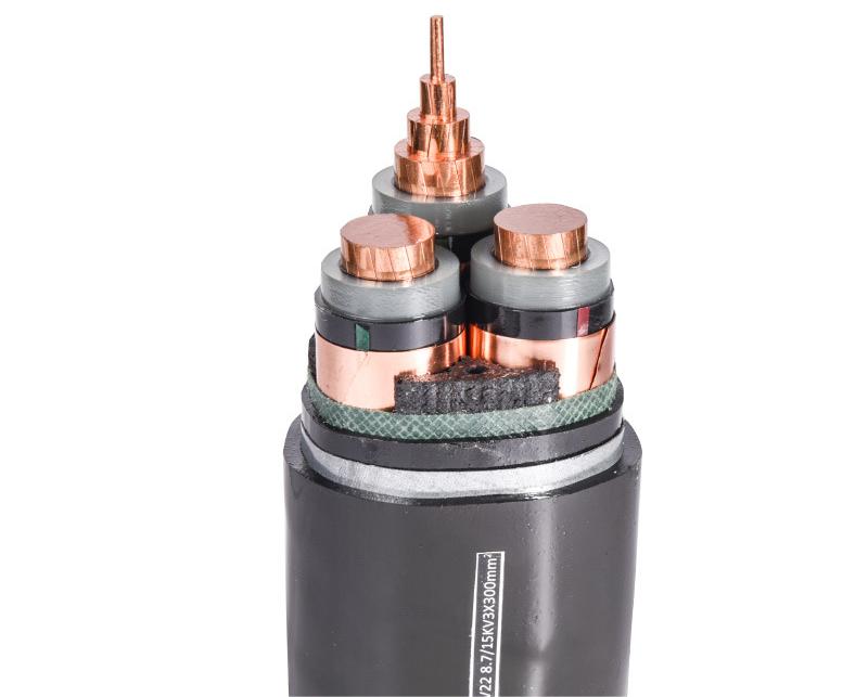
Medium voltage cable refers to the cable with a rated voltage between 1 and 35 kV, which is generally used for urban power supply, industrial and mining enterprise power consumption, and rural power grids. In order to confirm that the medium voltage cable line meets the quality requirements and ensures the safe operation of the line, the cable needs to be tested.
So how do you test the medium voltage cable? The voltage test is a common method for the operation department to check the strength of the cable. The voltage test can effectively check the local defects, such as bubbles and mechanical damage in the cable insulation, and reflect the aging and moisture of the cable insulation. According to the different test voltages, the cable voltage test is divided into a DC voltage test and an AC voltage test.

Local defects such as bubbles and mechanical damage in medium voltage cable insulation can be checked through a DC voltage-withstand test. DC leakage current measurement can reflect insulation aging, moisture, and other defects so as to judge the insulation condition. However, according to some operating experience at home and abroad, if the DC voltage is applied to the cross-linked polyethylene cable, then the DC test process will form a space charge in the cross-linked polyethylene winding and its accessories, which has an accumulation effect on the insulation, accelerates the aging of the insulation, and shortens the service life. At the same time, the distribution of the insulating electric field under the DC voltage is different from the actual operating voltage. Moreover, after the cross-linked polyethylene cable qualified by the DC test is put into operation, insulation accidents will occur under the normal working voltage. However, by applying the AC test voltage, we can prevent these shortcomings and accurately determine the normal insulation level. Therefore, the relevant people suggest that in addition to the 10KV, 1min DC voltage withstand test for the XLPE (the cross-linked polyethylene) sheath, the AC voltage withstand test with a 0.1Hz ultra-low frequency is also added.
Test method for the DC voltage resistance of cables
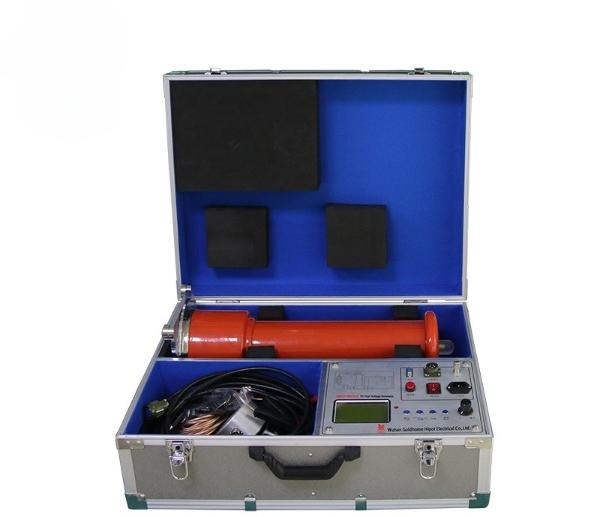
The DC voltage-withstand test of the cable can be tested by the DC high-voltage generator. The voltage and ammeter of the ZGF DC high voltage generator are on a digital display; the voltage resolution is 0.1 kV; the current resolution is 0.1 uA; the voltage meter on the control box directly displays the voltage value added to the load test; there is no additional voltage divider; simple wiring. The instrument has a high and low voltage end to measure the leakage current, and the high voltage end is displayed by a circular shielded digital meter, which is not afraid of discharge impact, has good anti-interference performance, and is suitable for field use.
(1) According to the test wiring diagram, one person conducts the wiring, and another person checks after the wiring, including whether there is any error in the test wiring, whether the measuring range of each instrument is appropriate, whether the field layout of the test instrument road is arranged, and whether the position of the test personnel is correct.
(2) The cable is fully discharged, indicating that the instrument is set to zero, and the regulator is placed in the zero position.
(3) Measure the power supply voltage.
(4) Close the power switch, start the equipment, power up the booster circuit, and gradually boost the voltage to the pre-determined test voltage value; Stay for 1 minute at 0.25, 0.5, or 0.75 times the test voltage to read the leakage current value; at 1.0 times the test voltage to read the leakage current value for 1 minute and 5 minutes; and read the leakage current value for 10 minutes and 15 minutes when handing over.
(5) After the test is completed, the regulator in the booster circuit should be returned to zero and the power supply cut off.
(6) After each test, the cable must first be discharged to the ground through the resistance and then directly discharged to the ground. When discharging, the insulation rod should be used, and the insulation condition can be roughly understood according to the size of the discharge spark of the phase tested.
Judging standard
For insulated cables, the leakage current imbalance coefficient of the three phases should not be greater than 2, 6 or 6 kV, 6 or 6 kV, and below the leakage current of the cable is less than 10 uA; at 8.7 or 10 kV, the cable leakage current is small (20 uA); the imbalance coefficient is not specified.
During the pressurization process, the leakage current changes suddenly, increases with the growth of time, or increases disproportionately with the rise of the test voltage, indicating that there are defects in the cable insulation, and the cause should be further identified. If necessary, the voltage time can be extended or the voltage value can be increased to find insulation defects.
The leakage current between the two phases is very different, indicating that there may be a local defect in the insulation of a certain core cable.

Test method for the AC voltage resistance of cables
(1) Check that the test power supply, voltage regulator, and test transformer are normal. Prepare the test by connecting the coil to ensure that all test equipment and instruments are correctly connected and correctly indicated.
(2) After all equipment and instruments are connected, the protection gap is adjusted under no-load conditions, and the discharge voltage is within the range of 110%–120% of the test voltage (such as with the use of series resonance, another transformer regulation protection gap is required). And adjust the test voltage, maintain it at 5% higher than the test voltage for 2 minutes, reduce the voltage to zero, and open the power supply.
(3) Short circuit on the high voltage side through the current-limiting resistor R to adjust the reliability of the overcurrent protection trip.
(4) The voltage and current protection debugging check is correct, and after the wiring of various instruments is correct, the high-voltage lead can be connected to the winding under test.
(5) The voltage boost must be started from zero; the opening voltage speed is not limited within 40% of the test voltage; and then the voltage should be uniformly boosted; the speed is about 3% of the test voltage per second. Maintain the time specified in the regulation after raising the test voltage.
(6) Drop the voltage to zero, open the power supply, and the test is over.
Judging standard
If no disruptive discharge occurs during the test, the test is considered to have passed.

 Home
Home Will The Rising Cable Copper Price Turn International Speculators Into Lambs To The Slaughter?
  You May Also Like

 Tel
Tel
 Email
Email
 Address


